Split-Phase Installation
This chapter assumes the reader has read the CT Basics section.
What is split-phase?
Worldwide, virtually all of the residential power delivered to residential homes is 230V-240V single phase. In North America, the single-phase 240V supply is split so that there are two 120V legs that are typically used for lighting and light-duty appliances. To learn more see the Split-Phase Wiki.
Split-phase load centers
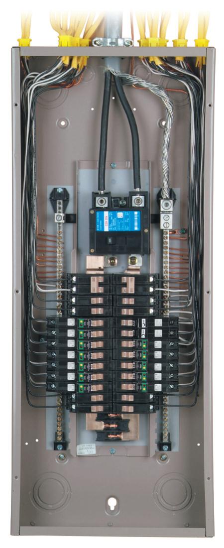
Maybe neater than normal load center
A typical split-phase load center has two Main circuit breakers, one for each of the two “legs” coming from the service entrance. There is also a third neutral wire that is directly connected to the neutral bus - a long bar with holes and screws to connect conductors. Another ground bus is provided which is connected to a reliable local earth connection like a ground stake. In most entrance panels, but not sub-panels, the neutral and ground busses are “bonded” (connected together).
The service is typically described in terms of the amperage rating of the Mains circuit breakers or fuses. Most common are “100A service” and “200A service”.
See the North America section of this Load-Center Wiki. to see how the split-phases correspond to alternating breaker rows.
Monitoring split phase
When monitoring a circuit in a split phase service, it’s helpful to recognize exactly which of the mains circuits it is utilizing. There are three possibilities:
120V phase A
These circuits are two conductor (plus ground) and typically use a black conductor connected to the circuit breaker and a white conductor connected to the neutral bus. As described in the Wiki, circuit breakers in odd rows will be on phase A. Odd rows include breakers numbered [1,2] [5,6] [9,10]..etc.
120V phase B
Same as above, except circuit breakers will be in the even rows with breakers numbered [3,4] [7,8] [11,12]… etc.
240V
These circuits are typically larger appliances like Hot-Water, Range, Pumps, Electric Heat, Dryers, Heat-pumps, sub-panels, and Air-conditioners. They use two circuit breakers in adjascent rows, so one of the breakers is on phase A and the other is on phase B.
As explained in the CT Basics section, 240V loads can be two-wire or three-wire.
Two-wire loads typically use two conductor cable with the white and black conductors connected to the two circuit-breakers. For these circuits, a single CT can be placed on either one of the two conductors and the “double” box checked to indicate to IoTaWatt that the voltage is doubled to 240V. Orientation of the CT is dependent on the row that the CT is associated with.
Three-wire loads typically use three conductor cable with black, red, and white conductors. The red and black are connected to the two breakers and the white is connected to neutral. These loads must be measured with two CTs, one on the red and one on the black, or by passing the two conductors through one CT in opposite directions so that the resulting orientation of the CT is correct for the row of the breaker that each conductor is connected to. An illustration can be found in the CT Basics section.
Voltage Reference
The voltage between the two mains conductors is nominally 240V. That is broken down into two 120V potentials between each of the Mains and the neutral, but unless they are in perfect balance, there will always be a difference in voltage between the two phases. That said, the difference in most situations is practically negligible and the sum of the two will always equal the voltage between the two Mains.
This is an important point, because in order to measure real-power, what your meter measures and what you pay for, it’s necessary to also have a reference voltage on that circuit.
IoTaWatt supports multiple voltage references, but as a practical matter, you only need one to measure any of the three circuits described above.
The simplest and most effective reference is a 120V wall transformer connected to an ordinary 120V plug as close to the load center as possible. That will provide a reference for the phase it is plugged into, and a reference that is the exact opposite of the other phase, or to put it another way, the reverse of the other phase.
Mains CT orientation
The first CTs to be installed should be the Mains.
As mentioned in multiple discussions, this is a job for someone familiar with the working with live, partially exposed electrical wiring and familiar with all of the risk factors. An electrician is recommended.
Because each of the Mains is on a different phase, and we are using the same voltage reference for both phases, we need to reverse one of them so that the current it measures aligns with the reversed voltage reference. So which one? The answer is that because the wall transformer plug is not polarized as well as other uncontrolled factors, we don’t know yet.
So what we do is just install the CTs with opposite orientation, configure them, and look at the status display of the IoTaWatt. If reversed, they will show a ↺ symbol. To correct this, you can do one of two things.
Reverse the wall transformer in its socket.
Click the “reverse” box in the VT configuration menu.
Now, the two Mains inputs should show the Watts for each Main and no reverse ↺.
Load CT orientation
First, it’s important to note that the only consequence of installing a load CT backward is that it will show a ↺ symbol next to the input in the status display. This indicates that IoTaWatt has recognized that the voltage and current are opposite and is producing the correct measurement by reversing the output numerically. There is no error attributable to this correction. If the ↺ symbol doesn’t bother you, you can place the CTs without regard for phase.
Another approach is to simply install the CTs without regard for phase orientation and then simply check the “reverse” box for any inputs that show the ↺ symbol in the status display or physically reverse those CTs in the load center.
To install with correct orientation initially, the easiest method is to install one CT on an active circuit and note if the ↺ symbol appears in the status display. If so, reverse that CT. Now note which way the correctly oriented CT is installed and whether its row is even or odd.
If it’s an even row, all of the CTs that you install on even row circuit-breakers should be installed with the same orientation and the odd row circuit breakers with the opposite orientation.