Configuring Power Channels (CTs)
What is a power channel?
Power channels measure the current flow through a circuit and combine that with the reference voltage to determine power, expressed in watts, and to accumulate energy used, expressed in watt-hours. Current through a circuit is measured indirectly by installing a passive sensor, called a current transformer (CT), around one of the conductors in the circuit. CTs come in a various capacities, physical connection type, and electrical output.
The good news is that IoTaWatt supports a wide variety of readily available CTs, and many can be configured simply by selecting the model from a list. CTs are connected with 3.5mm stereo jacks (headphone jacks). The CTs that are sold at the IoTaWatt stuff store are manufactured with 3.5mm jacks.
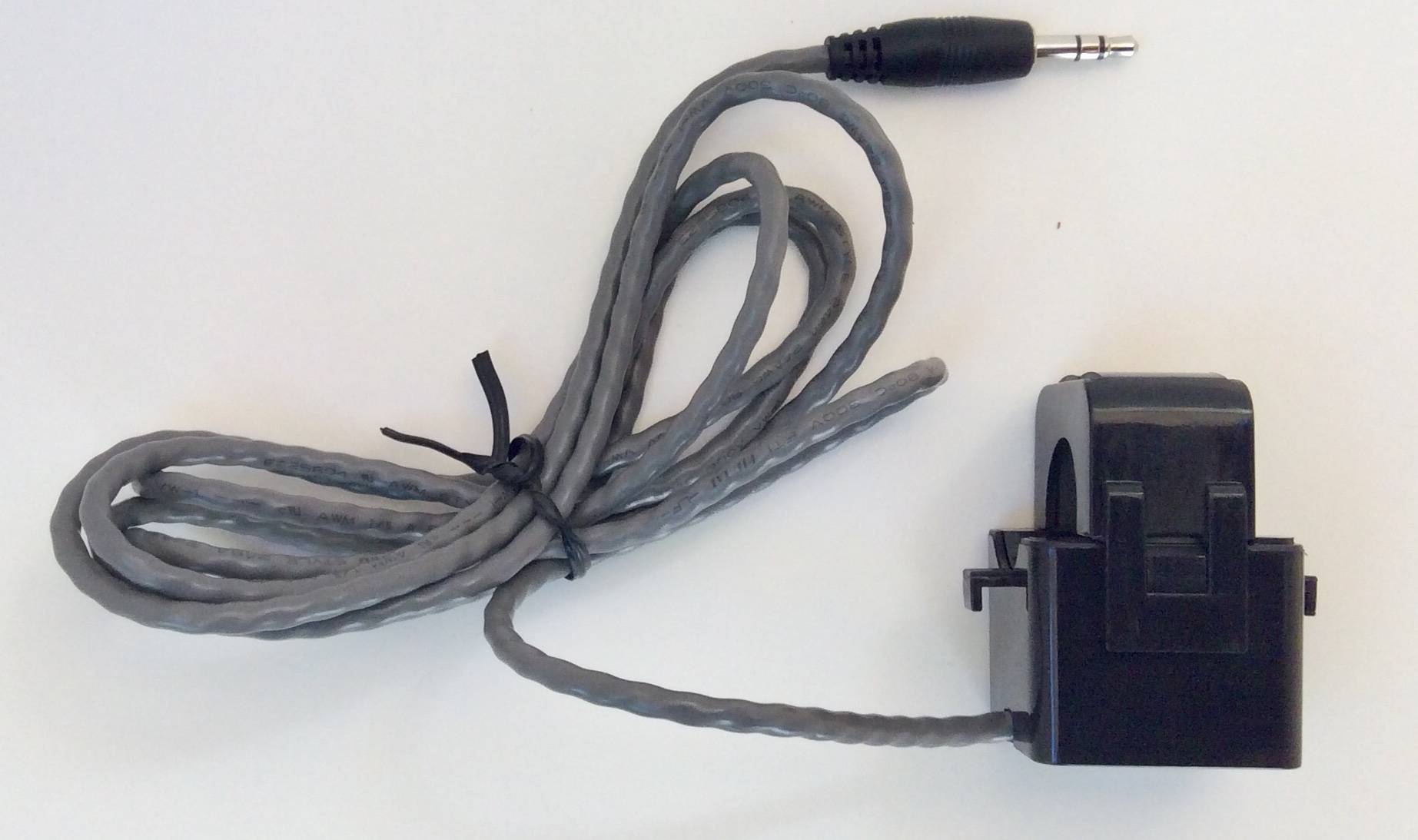
Echun ECS16-100 CT
Connecting the CTs
This tutorial does not cover physical installation of the CTs to your electrical circuits. That should be done by someone familiar with electrical wiring. Your qualified installer will know how to do this. The 3.5mm connectors plug into any of the 14 input channels on the IotaWatt.
The only additional recommendation is that all of the CTs be oriented the same way with respect to current flow. Most CTs have an arrow or other marking to aid in consistent orientation. Not to worry, in the event some end up backward, IoTaWatt will still work, will tell you which ones appear to be backward, and provides a way to correct virtually.
You can find more detailed information about physical installation of CTs in the CT Basics section.
Configuring the Input Channels
At this point, you should have the IoTaWatt up and running with the voltage
channel connected, configured, and calibrated if necessary.
You are using the config app in a browser connected to your WiFi network.
Hover over  and click
  in the dropdown buttons.

This screen should look familiar. We came here to configure the voltage
transformer (VT). Now we will configure current transformers (CTs) to other
inputs. To add or edit the CT specification for an input channel,
click the channel’s number button. Let’s add a CT to channel  .
.
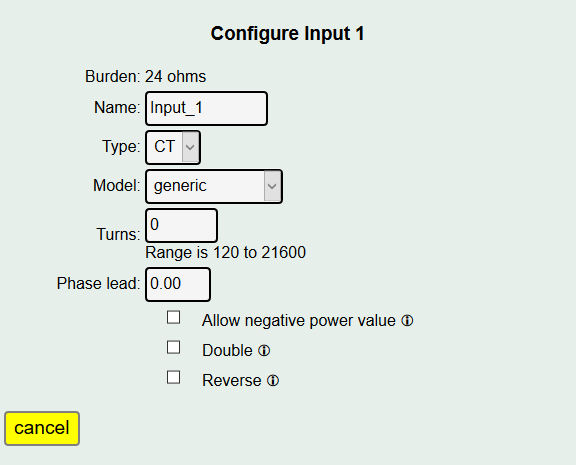
The app enters channel edit mode. Here you specify the model and other details about the CT connected to this particular channel. But first, it is helpful to name the channel by typing a name in the name box. You can just use the default “Input_1” or something more meaningful like “Kitchen” or “Living Room” or “Main”. We will configure one of our US 120/240V split-phase mains as main_1.
The default type is CT and that’s correct.
The next drop-down box is the model of the CT. Initially it will be generic, Click the drop-down list and select the ECS24200 CT.

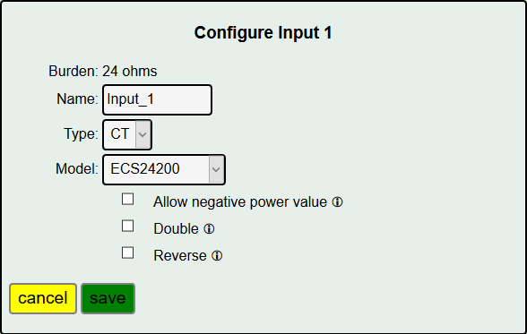
Notice that after selecting a specific device from the table, the input fields for “turns” and “phase” disappear. That’s because those values are known for the listed CTs. If you have a CT that is not found in the list, you will need specify the “generic” entry and provide the turns-ratio and phase-lead for that CT. see generic CT below.
There are check-boxes to further configure the CT. Most of the time, these will not be used, but there are circumstances where you would check one or more of them. If you hover on the ! next to each, a brief description will appear. They are explained below:
- Allow negative power value
- This is typically checked only for mains in an installation with grid-tied solar (net-metering). Checking this box tells IoTaWatt that it is normal for current to flow backward through this circuit, as when a PV system creates more power than you are using locally and the balance is “exported” to the grid. When you check this box you are affirming that the CT is installed correctly and that negative power should not be automatically “corrected” to positive.
- Double
- In North American split-phase power systems (120V/240V), all circuits are assumed to be 120V. When this option is selected, power will be computed using double the value of the reference voltage, or nominally 240V. Use this for 240V circuits where one CT has been applied to one of the conductors and there is no neutral (white) wire used by the appliance. Typical circuits would be Water Heater, Water Pump, Mini-Split Heat-Pump. There are other ways to monitor 240V circuits as well.
- Reverse
- Sometimes a CT is installed backwards with respect to normal current flow. IoTaWatt will sense this and correct automatically in single-phase power systems. It will correct the negative value automatically and indicate so in the status display with a little ↺ symbol. Selecting this option will virtually reverse the CT as if it were oriented correctly, obviating the need to physically reverse it. Doing so can be safer and/or easier, especially with solid core CTs. While merely convenient for single-phase systems, correct orientation is a necessity in three-phase installations because the IoTaWatt cannot automatically sense a reversed CT and correct for it.
Press  to finish.
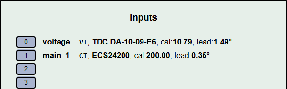
That’s it. The screen returns to the complete list of inputs where you can add more channels or change the configuration of existing inputs. Each time you press save, the new configuration is sent to IoTaWatt and the changes take effect immediately. If the CTs are installed and connected, you will can see the power displayed in the Input Channel Status screen.
When you have configured all of the CTs connected to the IoTaWatt,
basic configuration is complete.
Click the  button to see the IoTaWatt in action.
The following additional information may provide guidance for more advanced installations.
Generic CT
We just configured a Current Type CT that was of a model known to IoTaWatt. If your particular CT is not one of the dropdown models, you will need to describe the generic parameters. You will recall that this is the initial model designation for a CT when a new channel is added. Its also a drop-down choice when editing a CT channel. With this model selected, you must specify additional information depending on the type of CT:
Current Type CT
Current type CTs are the most common type of CT used with IoTaWatt and all of the CTs available in the IoTaWatt Stuff Store are of this type. They are typically described by the ratio of the maximum primary current that they can measure and the corresponding secondary current that will be produced, as in 200A:50mA. For these CTs, you will be asked to specify the “Turns:”. This is the ratio of primary current/secondary current. So that 100A:50mA described above would be 100/.050 = 2000 turns.
Voltage Type CT
Voltage type CTs are typically described with an output in volts (V) and have an internal burden resistor that causes them to produce an output voltage rather than current. They are connected to a modified IoTaWatt input that has had the internal burden resistor removed and specified as zero in the device configuration burden menu. IoTaWatt will ask for a Cal factor. This is the primary current in amps that corresponds to 1 volt of output from the CT. An example of this is the SCT013-050 from YHDC. It is marked 50A/1V, so the Cal is 50. Simple enough.
Phase
Both of the generic CT types above will also provide a place to specify Phase. Representative samples of the CTs in the model list have been tested to determine a phase correction value to compensate for phase shift of the transformer. If you have a generic CT a rule of thumb would be to use 2.0 for a split core CT (one that snaps onto a wire), and 0.2 for solid core CTs (Basically a solid doughnut that you pass the conductor through).
Enable derived three-phase
This checkbox enables advanced features used to configure inputs in a three-phase power system. Refer to the section Three Phase Power for more information.