Three-phase Power
IoTaWatt has the capability to measure power in polyphase systems. In the interest of keeping the user interface simple for the majority of users with single phase power, the details are disguised and/or hidden until needed. There has been a lot of interest in using IoTaWatt for three-phase monitoring, particularly in three phase countries like Australia and Germany. For home energy monitoring, the derived reference method is very popular.
This chapter explains two methods for measuring a so calld “four wire” or “wye” system, by far the most common implementation of three-phase. IoTaWatt can also be used with “three wire” or “delta” systems using different methods.
As explained in the introductory single phase section, a voltage reference is needed to measure real power. The challenge with three-phase power is to obtain three different voltage/phase reference signals. IoTaWatt can do this by two different methods:
Direct Reference uses three discrete voltage transformers or VTs, each one plugged into a circuit on a different phase. The primary advantage is voltage accuracy, while the disadvantages are that the extra VTs add cost, require using two of the inputs, and require plugs on each phase in proximity to the IoTaWatt.
Derived Reference uses a single voltage transformer and derives a reference voltage/phase for the other two phases by numerically shifting the phase of the single reference by 120° or 240°. The primary advantage is low cost and convenience of installation. The disadvantage is that large variations in voltage between phases may result in decreased accuracy.
Configuring Direct Reference
Connecting additional VTs
To use Direct Reference three-phase power measurement, it’s necessary to install two additional VTs (total of three), and to plug each of them into a receptacle that is supplied by a unique phase.
Version 5 of IoTaWatt, available second quarter 2019, will have native plugs to connect the additional VTs. This tutorial will assume you have the new version 5 IoTaWatt.
The additional VTs will plug into two sockets at the rear of the unit. They are labelled VT-13 and VT-14. When these are used, the standard channel 13 and 14 jacks should not be used.

Configuring the voltage inputs
Now the additional VTs can be configured and calibrated. Do this in the same way that the first VT was configured. Click the channel number, click “VT” then specify the model. Click Calibrate and calibrate the voltage to match your reference. It’s not necessary that the VTs be plugged into their eventual phase for this step. If you have two outlets on any of the phases, use those to plug in each VT in turn along with a voltage reference while you calibrate. Once calibrated, the VTs can be moved to the appropriate phase/socket.
Name each of the phases to uniquely identify each reference. You can use phase_A, phase_B etc., or maybe use the color coding of your system to be more descriptive - voltage_red, voltage_black, voltage_blue (US).
Configuring the CTs
Now start adding your CTs. The twist here is that because more than one VT is configured, an additional selection box is displayed to specify which VT is associated with the phase of that particular CT.
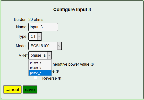
If your service is consistently color coded, you should know the phase by the color of the conductor that you clamp the CT onto.
Configuring Derived Reference
Another way to approach the voltage reference problem in three-phase is to use the voltage/phase reference of one phase to derive a reference signal for the other two. While not as exact, this method can produce good results. The IoTaWatt numerically shifts the single voltage/phase reference by 120° or 240° to measure power on the additional two legs. Using this method, a three-phase system can be monitored with a single VT, just as with single-phase systems.
This chapter explains how to configure IoTaWatt to use “Derived Reference”. It’s pretty straightforward.
Configure the VT
Set up your IoTaWatt with the voltage reference VT on whatever phase of the three-phase is convenient. We will call that phase A. This is important:
However you identify your physical phases, IoTaWatt always identifies the phase that the VT is connected to as phase A.
The other two virtual phases will be phase B and phase C. It doesn’t matter where which of the physical phases your VT is connected to. Your starting point is always A.
There are color coding schemes for the phases, but they vary so widely that I’m not going to try to reconcile this scheme with any of them. That exercise is left to the reader. The good news is that you really don’t have to know what any of the phases are to complete this setup.
Configure the CTs
Connect CTs to each of the circuits that you want to measure, and configure them as described here.
Be sure to orient all of the CTs the same way with respect to source and load.
The following instructions will not work as described if any CTs on the derived phases are reversed.
If you’ve done everything correctly, your IoTaWatt status display should be displaying the correct power for all of the circuits on phase A, and roughly half power for all of the circuits on phases B and C.
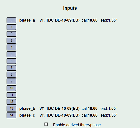
Now in the input configuration menu, click the box for “Enable derived three-phase” at the bottom.
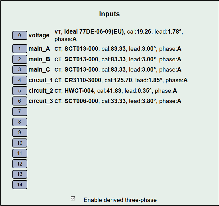
The configured input channels should now have “phase:A” appended to their descriptions. Go to the status display and evaluate which of the inputs appear to be showing power that is half what is expected. Note them and go back to the input configuration screen. If you know the relative phase of your circuits, you can just specify them now and fast-forward over this “trial and error” approach that follows.
Edit each of the incorrect inputs in turn, changing the “Mains Phase” to phase B.

Now go back to the status display and see which inputs still appear to be about half of the expected value, go back to the input menu and change those to phase C.
The status display should now indicate the correct power for all of the phase.
This procedure works best when the loads are substantial and have high power factors.
One additional point. Once you configure inputs to indicate mains phase B or C, the “Enable derived three-phase” checkbox will remain set and cannot be turned off until all of the inputs are reconfigured back to phase A.
Reporting Power
Once all of the VTs and CTs are configured, there are several ways to view the power used. For circuits and/or loads that use only one phase, the power value displayed for that channel should be correct as is. If there are devices that use two or three of the phases, you must add the power from each of the phases to get total power. For each such device, define an output channel and use the calculator to specify adding the component channels. If you are reporting the data to a server, the data can be tailored with the calculator to send the single combined aggregate power for those devices.